PIPE SIZING IN HVAC
Pipe is a conduct or a medium through
which any liquid or gas can be passed.
Well similar to duct it is a kind
transferring medium through which gas or liquid is been proceeded.
Pipes are very important part
in transferring the required liquid or gas to required place with the presence
of pressurised pump system which maintains required pressure to flow the liquid
to desired point.
Well as we know that either it
may be cooling or heating of an area it is not possible and economical to place
a different cooling system everywhere hence pipes conduct and takes the responsibility
to transfer the liquid or gas medium to required point.
Well the responsibility of the
pipe are to supply the cool water and bring the hot water back to the system
and repeat this process continuously as an cycle.
AIR CONDITIONING PIPING SYSTEM
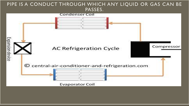
In an air conditioning system
the pipe which joins compressor ,condenser, expansion valve and evaporator
through which refrigerant is passed is called primary refrigerant.
Generally the pipe material
used in this air conditioning system are copper.
Well the copper which are used
are depending on the amount of capacity and the pressure resisting capacity of
an air conditioning system which are made of copper material ,which is soft
copper for up to 2 TR system and above 2
TR hard copper is used.
Well the above system where copper
is used are generally for air conditioning system.
CHILLER PIPING
SYSTEM
In chiller system there is
additional piping which joins pump, FCU or AHU and chiller in which chilled water is been
supplied is called as secondary chill water piping.
CHILLER CONDENSER PIPING
SYSTEM
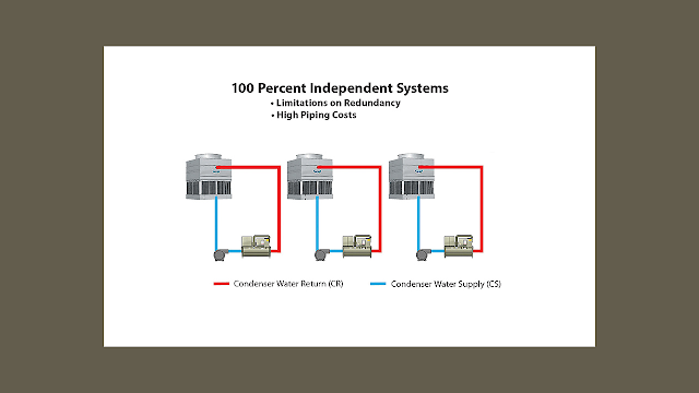
The condenser piping are
generally seen in water cool chiller system which connects pumps, cooling tower
and shell and tube condenser is called open piping or hot water system.
MATERIALS IN
CHILLED WATER PIPING
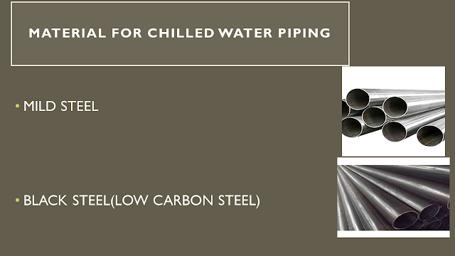
In chilled water system there
are generally two type of material used
Mild steel M.S:
Black steel (low carbon steel)
ARRANGEMENT OF CHILLER PIPING SYSTEM
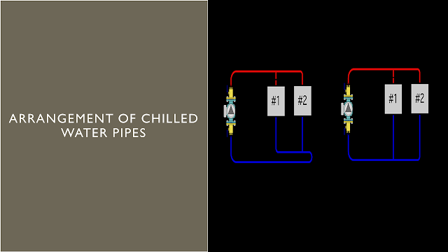
Well chilled water pipes are
generally arranged in two ways:
TWO PIPE DIRECT
RETURN SYSTEM
Well have a look at the second
arrangement which is called as two pipe direct return system.
From figure you can see the
pumps are been connected to the AHU system via pipe connection.
Basically in this system blue
coloured chill water is been supplied to the AHU 1 and than to AHU 2 while taking away the used
or evaporated water again from AHU 1 and AHU 2 in red colour line.
Hence this system is not
hydraulically balanced because the amount of pressure absorb by the AHU 1 is
more compared to AHU 2 as we know the flow rate decreases with the coverage
length of fluid flowing in the path.
While the extraction of water
is also taken place at AHU 1 firstly and than at AHU2 hence this system is not
hydraulically balanced.
If the system is not
hydraulically balance there are chances of pipe getting leaks and reduce its capacity
to hold the pressure of water flowing in it.
Hence to overcome and maintain
hydraulically balance system we need to focus on proper systematic arrangement.
TWO PIPE REVERSE SYSTEM
Well have a look at the first
arrangement which is called as two pipe reverse return system.
From figure you can see the
pumps are been connected to the AHU system via pipe connection.
Basically in this system blue
coloured chill water is been supplied to the AHU 2 and than to AHU 1 while
taking away the used or evaporated water again from AHU 1 and AHU 2.
Hence the system is
hydraulically balanced and there are less chances of getting leakage due to
uneven pressure .
This is very important part in
arrangement , because it not only hydraulically balance but increases the life
of the whole system by contributing to avoid losses of financial bones of a
project.
CLASSIFICATION OF
PIPE
ACCORDING TO MAUNFACTURING
SEAMLESS PIPES(CONTINUOUS
PIPES WITHOUT WELDING JOINTS)
GENERALY USED FOR REFRIGERANT
PIPING TO AVOID LEAKAGE AND WITHSTAND HIGH PRESSURE UPTO 40 BARS)
WELDED PIPES (GENERALLY USED
FOR CHILLED WATER,HOT WATER,PLUMBING AND FIREFIGHTING)
ACCORDING TO CLASS
CLASS A OR SCHEDULE 20 OR LIGHT
DUTY
CLASS B OR SCHEDULE 40 OR
MEDIUM DUTY
CLASS C OR SCHEDULE 60 OR
HEAVY DUTY
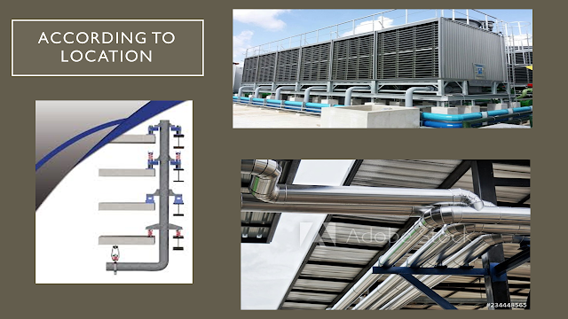
ACCORDING TO LOCATION
ROOF ( VELOCITY 10FPS)
RISER(VELOCITY 7 – 10FPS)
FLOOR(VELOCITY 5 – 7 PFS)
MAX VELOCTY 15 FPS
MIN VELOCITY 1.5 FPS
This are the data from carrier
handbook data book.
Well maximum velocity which is
15 FPS (feet per second)is to avoid erosion and increase the life of the
system.
And minimum velocity in
chilled water should not be less than 1.5 FPS(feet per second) in any pipe.
In chilled water pipe sizing before
designing it is necessary to know what is the capacity of system.
As we know in normal air conditioning
system when heat load is calculated generally the term used is how much ton of
capacity ?
similarly a whole chilled water system also have capacity which is
also denoted in terms of tons of capacity or TR.
But to find the pipe size one
need to know the GPM of pump system .
So let find it!!!!!!!
CHILLED WATER
PIPES(CHILLER TO AHU)
FLOW RATE IN GPM
1GALLONS = 3.78 LTR
GPM=TR X 24/∆T
1 TR =2.4 GPM (IF ∆T IS 10)
CONDENSER COOLING
PIPES(CHILLER TO COOLING TOWER)
FLOW RATE IN GPM
1GALLONS = 3.78 LTR
GPM=TR X 30/∆T
1 TR =3 GPM (IF ∆T IS 10)
Well there are two case
If the pipe has to be sized for
chilled water system from AHU to chiller than 1 TR =2.4 GPM (IF ∆T IS 10)
If the pipe has to be sized for
chilled water system from cooling tower to chiller than 1 TR =3 GPM (IF ∆T IS 10).
PIPE SIZING METHODS
CONSTANT VELOCITY
METHOD
VELOCITY AND
FRICTION METHOD
This are the two methods which
are generally used in pipe sizing or pipe designing method…
CONSTANT VELOCITY METHOD
As the name suggest in this
method the velocity of the fluid assumed
to be constant which have different value for different location …
ROOF ( VELOCITY
10FPS)
RISER(VELOCITY 7 –
10FPS)
FLOOR(VELOCITY 5 –
7 PFS)
So lets take an example so to understand
more clearly…
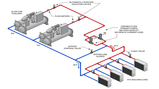
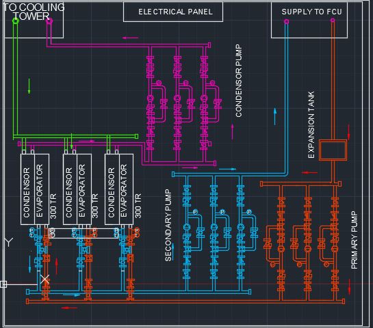
From the above diagram lets
have a look at the chilled water plant
Chiller which has two section
(condenser and evaporator).
CHILLER EVAPORATOR is the
space which consist of chilled evaporator coils in a shell and tube device
which chilled the water by absorbing the heat from it and this chilled water is
passed to the AHU or FCU via pump suction and discharge pressure.
CHILLER CONDENSER is the space
similar to evaporator space which consist of condenser unit where the refrigerant
heat is removed by exchanging the heat in condenser unit via supply of water cycle
in connection with pump line to the cooling tower where the hot water is cooled
.
So lets take an example of
four storey apartment having 900 TR cooling load i.e 540TR per floor
So lets find out the Total GPM
required..
1 TR =2.4 GPM (IF ∆T IS 10)
assuming std temperature difference
900 x 2.4=2160 GPM
AS we know that as per the
location velocity is constant
So lets used pipe sizer …by
selecting the following
Pipe class schedule 40
70°F water
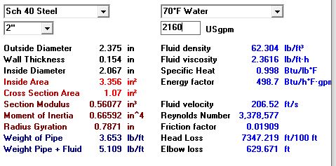
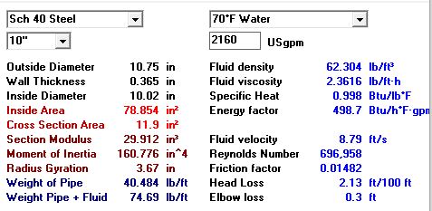
2160 GPM, we get the following data for riser pipe till
AHU 1
RISER
1)Q=2160GPM VMAX=10FPS
V= 8.79FPS(less than 10FPS) DIA=10``
hl=2.18``/100``
From above figure velocity is 8.79FPS for
10`` diameter if the velocity is more than 10`` it wont be accepted.
Similarly 2)Q=1620GPM VMAX=10FPS
V=6.59 fps DIA=10``
hl=1.2``/100``
3)Q=1080GPM VMAX=10FPS V=6.93fps DIA=8`` hl=1.8``/100``
4)Q=540GPM VMAX=10FPS V=8.66fps DIA=5`` hl=4.87``/100``
3)Q=1080GPM VMAX=10FPS V=6.93fps DIA=8`` hl=1.8``/100``
4)Q=540GPM VMAX=10FPS V=8.66fps DIA=5`` hl=4.87``/100``
This is all data for riser pipe size as
per the GPM , as the GPM decease the pipe size too decreases.
FLOOR
FLOOR(VELOCITY 5 –
7 PFS)
1)Q=540GPM VMAX=6FPS
V=6fps DIA=6`` hl=1.94``/100``
As every floor have same GPM so diameter
is also same having velocity lower than 6 FPS.
VELOCITY AND
FRICTION METHOD
As we know that in constant velocity method,
we avoid the friction consideration, for small size pipe and GPM it is suitable
but when it comes to heavy GPM the water tends to corroded the inner pipe
resulting in damage and leakage and ultimately break down of the project.
So to avoid it industry follows this
process … basically velocity and friction method is combination of both which
have certain condition when to used which method.
condition
1.velocity method
if diameter <=2``
velocity<=4fps
2.friction method
if dia >=2``
head loss<=4ft/100ft
well in this method velocity method is used
with diameter less than or equal to 2`` when the velocity is less than 4FPS ,
if its greater than we opt to friction method.
In friction method diameter should be
greater than 2`` and velocity is not the
concern here head loss is concerned which must be less than or equal to 4ft/100ft.
So lets take the same example.
VELOCITY AND FRICTION METHOD
RISER
1)Q=2160GPM
As we can see that with 2`` diameter
velocity is 206.52FPS , Which is against the condition1.velocity method =if diameter
<=2``,velocity<=4fps
Hence lets opt for friction method
1)Q=2160GPM DIA=10`` hl=2.18``/100``
This data is accepted according to the condition of friction method if dia >=2`` head
loss<=4ft/100ft
Similarly for others we get the following
data
2)Q=1620GPM DIA=8`` hl=3.9``/100``
3)Q=1080GPM DIA=8`` hl=1.8``/100``
4)Q=540GPM DIA=6`` hl=1.94``/100``
2)Q=1620GPM DIA=8`` hl=3.9``/100``
3)Q=1080GPM DIA=8`` hl=1.8``/100``
4)Q=540GPM DIA=6`` hl=1.94``/100``
FLOOR
4)Q=540GPM DIA=6`` hl=1.94``/100``
This is all about pipe sizing. Pipe sizing
is very important as the economical and safety condition need to followed for
optimised design of pipe size.
hope this article helped out to resolve your doubt....




please don`t enter any spam link in the comment box ConversionConversion EmoticonEmoticon